
CAD & CAM Tips and Tricks for Microfluidics CNC
Published by Alex Hwu & Ehsan Shamloo on Jan 25th 2025
With CNC machining, microfluidics prototypes can be made directly in rigid plastic and allow for faster iterations compared to conventional PDMS techniques. However, learning how to micromachine microfluidics can be intimidating due to the different aspects such as computer aided design (CAD), computer aided manufacturing (CAM), setup & machining, assembly, and finally, microfluidic testing.
Here are some tips and tricks when designing microfluidics for CNC machining
CAD: Z-axis Up
Make microchannels and chambers parallel to the z-axis to simplify the CAM setup. By default, SolidWorks defines the top plane perpendicular to the y-axis while Fusion 360 defines the top plane perpendicular to the z-axis. For one-sided microfluidics, make the features on the top face of the solid body extruded from the z-axis.
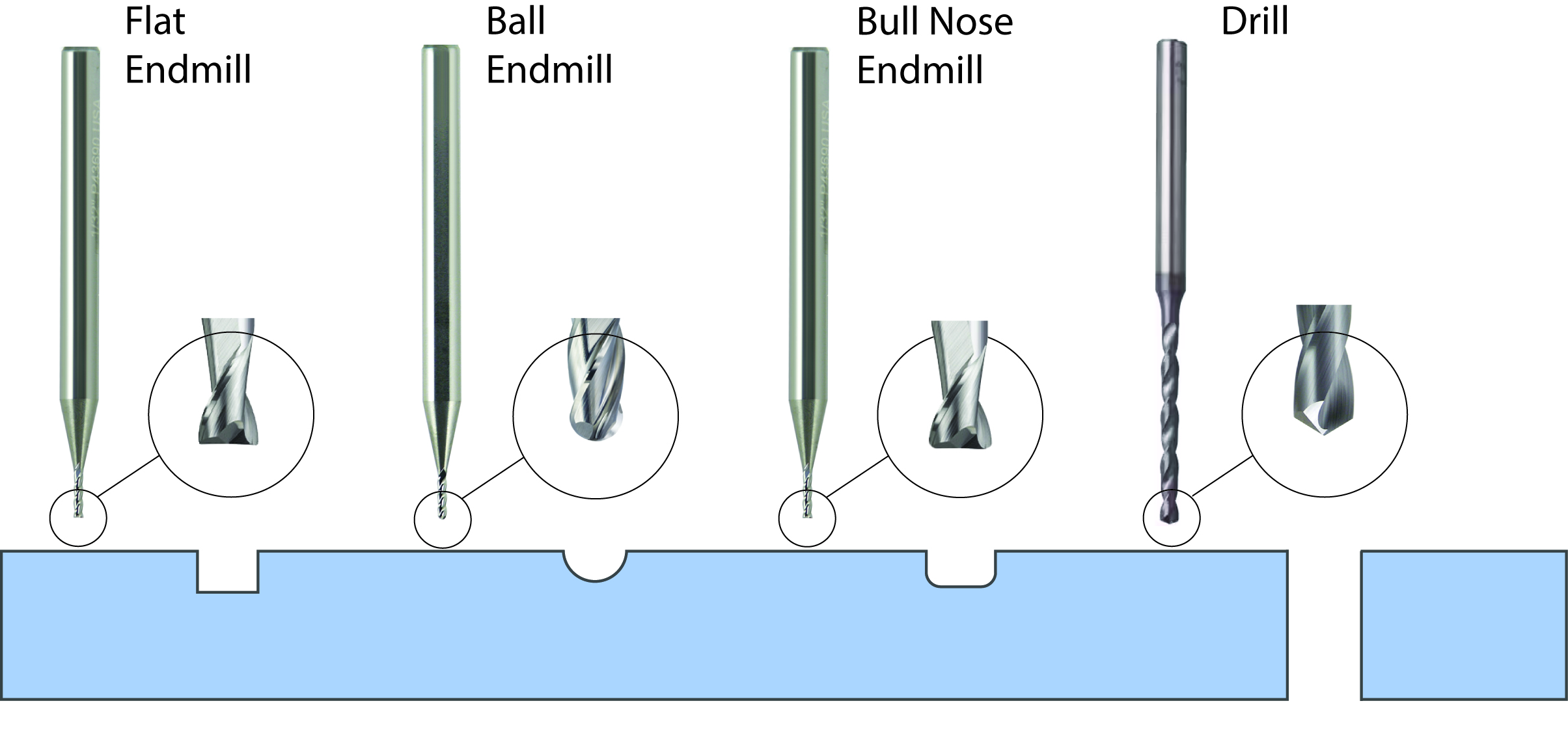
CAD: Think about the Tools!
Design with the tools in mind for an efficient CNC process. The primary CNC ‘tools’ used for microfluidics machining include flat end mills, drill bits, and sometimes ball end mills and are commonly referred to by their diameter. Small diameter tools (< 1/32” or < 0.8 mm) are fragile and require slower feed rates, resulting in longer machining times. Reduce machining time by matching feature width to tool size (e.g. use 1/64” tool to cut a 0.4 mm channel) or by using larger end mills to remove bulk material followed by a small tool for chamber definition. Below is a table of common tool diameters used in microfluidic machining. Precision will vary based off the tool manufacturer’s tolerance.
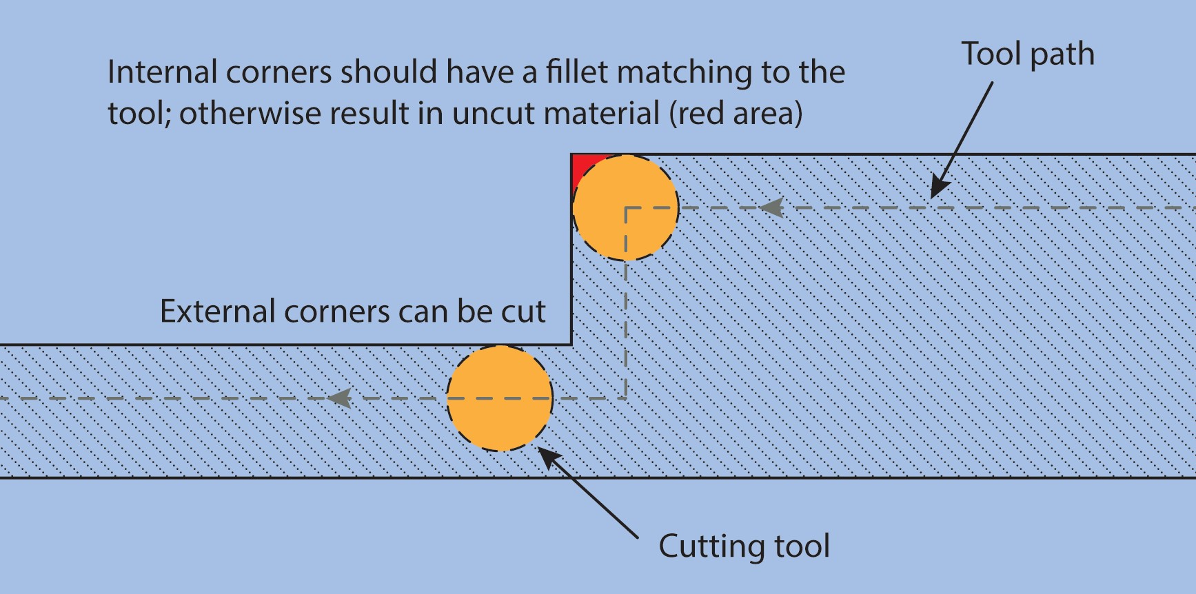
CAD: Minimize Sharp edges
Avoid sharp edges by applying fillets to any internal corners. This is primarily applicable to chamber design. For example, making a 10 mm x 10 mm (Length x Width) chamber using a ¼” end mill will yield a chamber with the internal corners of the chamber will have a radius of 3.175mm.
CAD: Use Thin Extrude (cut) to Simplify Microchannel Construction
Avoid constructing microfluidic channels by modeling the side walls unless absolutely necessary (example in video). Instead, make a line and use “extrude thin” from the “wall center” to define the channel dimensions. This reduces the number of steps needed to make a channel and makes it easier to modify channel geometries later down the road.
CAD: Fully define sketches
Assign proper dimensions and constraints to fully confine the model geometry. Floating dimensions and improperly defined relations will result in errors or disproportionate changes when returning to edit specific features.
CAM: Test Speeds and Feeds
Determining a tool’s speed and feed is an iterative process and is like optimizing fabrication parameters analogous to optimizing other process conditions (e.g. spin coating recipes, lithography baking temps/durations, SLA exposure settings, FDM temperature/speeds, etc).
These conditions can be evaluated by patterning the geometry intended for the tool and incrementally testing the speed and/or feed. Here, we patterned 400-micron width serpentine channels and increased the feed rate in 50 mm/s increments for our 300 micron end mill. Incorrect speeds and feeds will result in poorly defined cuts, excessive burrs, and repeated tool breakage.
CAM: Match Feature and Tool Width
Similar to designing with the tool in mind, reduce machining time by using larger tools when appropriate. Use a 0.5 mm end mill to make a 0.5 mm width channel. For microchambers, use larger tools to remove bulk material and smaller tools to define the chamber geometry.
CAM: Use Peck Drilling
Instead of cutting drilling holes in a single step, peck drilling follows an in-out-in-out motion minimize plastic accumulation. For example, a 1 mm hole depth drilled using peck drilling can be cut by drilling 0.5 mm depth, retracting, then reentering to finish the entirety of the whole depth.