Designing CD Microfluidics: Getting Started
Published by Alex Hwu on Feb 12th 2025
Centrifugal disc (CD) microfluidics offers a unique way to control on-chip liquid flow without the need for tubing or external pumps. Using a motor to spin the disc, centrifugal forces push the liquid, which are confined in chambers or channels, radially outward. Instruments designed to interact and spin the disc to control microfluidic flow make it possible to automate an entire assay from sample prep to result readout, making the CD a popular platform for point-of-care and in-situ testing.
Basic Design
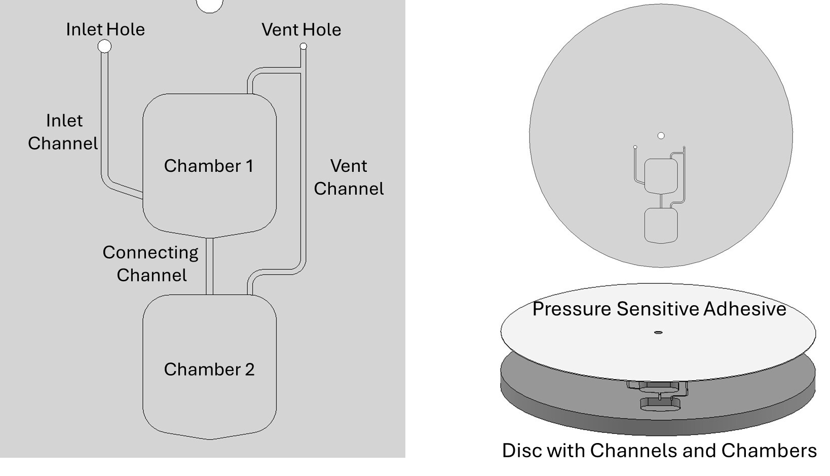
An example of a simple CD microfluidic design is given in Figure 1. The design consists of two chambers connected with a microchannel. The top chamber has an inlet channel connected to an inlet hole, which is accessed via pipetting from the back of the disc. Both chambers share a vent, an important feature to enable fluid flow onto and in the disc. These fluidic features are sealed off using a pressure sensitive adhesive* or can also be ‘lidded’ using a blank CD of the same profile via double-sided adhesive or ultrasonic bonding.

The example is a ‘workable’ design that addresses common mistakes when starting CD microfluidics. Each one is described further below:
Design Radially Outward:
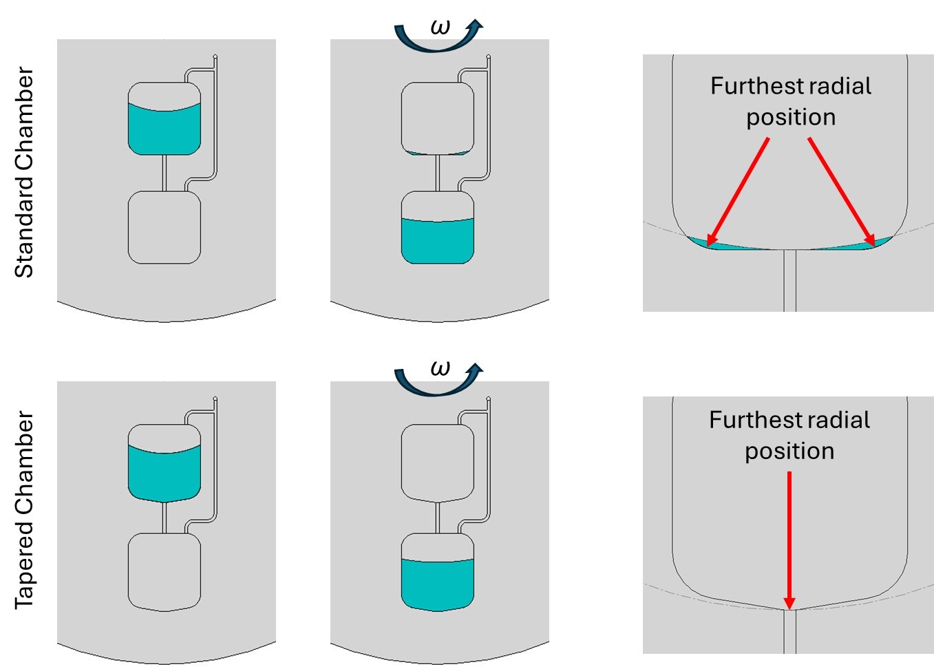
When rotating at a constant speed, often referred to by angular velocity (ω), the centrifugal force pushes liquid towards the farthest radial position. If a channel is not positioned at the outer most radial point of the chamber, liquid will remain trapped and potentially cause downstream assay variability. Taper the chamber so the outlet is positioned at the furthest radial position.

Don’t Overlook Venting:
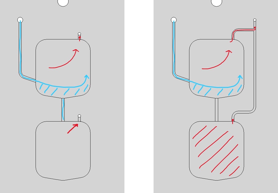
Venting is an important concept for CD microfluidics because there is technically no outlet for the liquid to escape. When liquid is transferred onto the disc, any air trapped in the chambers/channels must be exhausted via vents otherwise it becomes compressed, causing liquid to leak from the inlet.
Vents can be simple holes directly in the chamber or can be strategically combined. When combined, it’s important to consider how the chambers interact and how the gas is vented. The figure below illustrates two scenarios of gas venting (red) when introducing fluid (blue) onto the CD.

Introduce Liquid towards the Bottom of the Chamber:
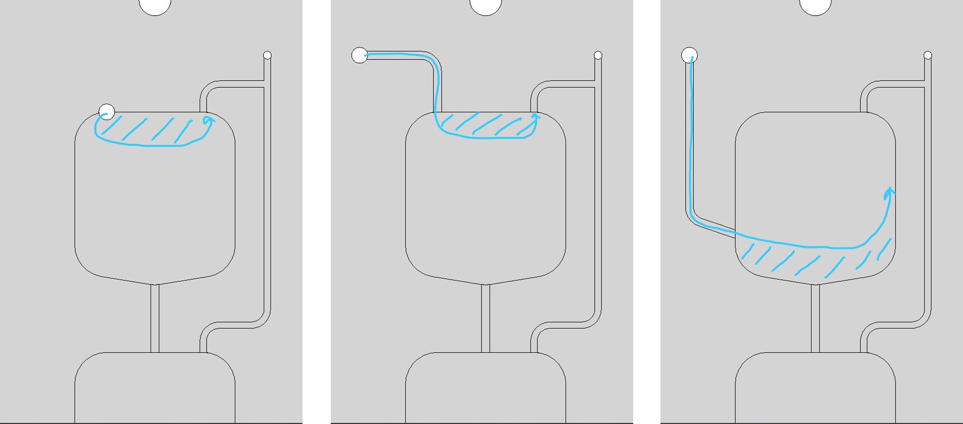
Transferring an entire volume of liquid into the CD can be tricky if the inlet is incorrectly placed. Liquid tends to stick to the surfaces of the disc (especially true with PMMA) so placing the inlet at the top of the chamber may cause the liquid to escape to the vent hole. To address this issue, use a channel to introduce the liquid near the bottom of the first chamber. 
*A popular pressure sensitive adhesive is 9795R made by Solventum (previously 3M) due to its chemical inertness and PCR compatibility.

